Thursday, December 16, 2010

Top Bar Hive - Progress

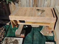
I'm loving my top bar hive. The bees seem to be loving at too. After my initial attempts to populate the hive failed I was a bit discouraged but its all go now. I've discovered a few design flaws (or design opportunities?) which I'll details a bit later.

There are two main features of the hive that increase the enjoyment for me. The first is the bees are so much calmer. I'm fairly careful about managing my queens so my bees are very calm normally anyway but being able to remove one comb at a time seems to agree with them. I assume that when a Langstroth hive is opened there is quite a draft that cools the entire hive, from bottom to top. This is not the case with the top bar. The second is no heavy lift while bending over the hive. I sit on a stool (upside down flower pot) for the duration of the inspection and can take all the time I like.

Progress
Bar 8, 24 October
Bar 8, 16 October
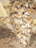
 These two photos were taken a week apart. The first shows the bees just starting to build on a new bar. In the second they have stopped building and start using it for pollen storage.


Bar 7, 16 October
Bar 7 also shows significant expansion. An inspection of the second photo reveals a small amount of capped honey and some freshly capped brood. These photos were taken four weeks apart. It is interesting to note how the comb shape has changed from round to matching the shape of the hive.
Bar 7, 7 November
 
Bar 9, 16 October
Bar 9, 7 November
The progress on bar 9 is more dramatic. This bar was moved from the far end of the hive to directly above the entrance on the 16th. The bees seem to have taken to the bars very readily.
Bar 9, 24 October


Design Flaws
Bowed Comb
There are two issues I have discovered so far. The first is a simple fix. The bars are grooved down the center then the groove is filled with wax. When I manufactured the bars I thought a patch of wax in the middle would be sufficient to encourage the bees to build in the correct place. This proved to be the case but once the comb was bigger than the patch of wax the bees avoided the groove, resulting in bowed combs. This has a knock on effect for the next few bars and some of the combs are overlapping bars because of this bow. This can be easily remedied by making the patch of wax larger but I don't want to encourage them to attach the combs to the side wall by making the patch too big.

The second issue is the installation of the viewing window. This is a CD case glued to the outside of the hive. This leaves a large recess in the wall, which the bees have expanded the combs into. The combs are not attached to the wall but they will not fit elsewhere in the hive. This makes it difficult to arrange the frames as I'd like, to encourage the growth of the hive. The next version will have to have another piece of window installed on the inside. I'm sure they won't complain about having double glazing installed.

Monday, October 18, 2010

Varroa Control - Drone Frame

As part of my varroa control strategy, if you can call it that, I inserted a drone frame into the brood chamber of my main hive, hive two. Drone take ~24 days to mature before emerging from the cell so the varroa are attracted to them. The extra 3 days increases the chances of another of the mother varroa's progeny reaching breeding age.

It wasn't fully capped but I didn't want the drone emerging and unleashing a flood of varroa on the hive. After removal I pulled 20 larvae and counted the mites on them. From this small sample I estimate that 1.5% of the drone brood where maturing while sharing a cell with a varroa mite family.

20 Drones, 3 female varroa
The chickens enjoyed eating the brood. Its not great for the bees because the chickens break the cells down so they have to be redrawn but I know none of the drones or their parasites survived.

The photo below shows a mother varroa mite and her male offspring. The male usually remain in the cell and have a very soft body. I'm guessing they don't like the sun either. This one is making a dash for the shadow on the tip of my thumb, under the larva.
My plan from here, once the new queen has begun laying, is to reinsert the drone frame and give the bees a month or so to repair the damage the chickens have done. By this stage there should be another frame of sacrificial victims so remove. I'll perform the same count and see how the numbers compare. I also need to put a sticky board under the hive and see what the natural mite fall is.

Sunday, October 17, 2010

Nuc and a swarm

It appears that when I made up my latest nuc I didn't select the brood frame very well. Around midday Saturday I noticed a lot of bee activity around a Kowhai tree in the natives corner. Closer inspection revealed a small swarm. I'd be surprised if this swarm lasted very long unaided especially given the cold nights we are having in Christchurch at present I set about collecting it.

A full inspected of the top bar hive yesterday had revealed no queen cells so the swarm can't have originated from there. The swarm looked too big to have originated from the nuc but that was the only option left. It seemed unlikely that some else's swarm had settled near my hives.

I'm always amazed at the bees ability to communicate. The Queen Substance must be a very strong smell for them. Whenever a swarm is knocked from its perch there is a lot of confusion, bees flying everywhere, but within a few minutes things calm down and the bees collect around the queen again. I placed a nuc box under the swarm, knocked them off and waited. It no time at all order replaced confusion and the majority of the bees were heading in the same direction, into the nuc box.

A queen, seconds after hatching
The nuc was well populated, prior to the swarm, to I took this to mean they wanted more space. I replaced the nuc box with a full depth super and transferred the remaining population, which was still significant, across. It didn't take long to confirm where the swarm had come from. The photo on the left clearly shows several supcedure cells. Most were ripped open but one was in tact. I cut it off and help the queen hatch. She then flew away so I don't know whether she survived or not.

A sheet of newspaper, then a half height box prepared the new hive more merger with the swarm. After dumping the swarm into the half height I slipped the lid on and left them to it. The queens will fight it out I suppose and since they are both new I have no opinion on which one would be better - may the best queen win.

Saturday, October 16, 2010

Hexapod - The Brain

My intention for this robot has always been to use the PIC chips as the computing power. Each leg was to be controlled by its own processor that knows just enough to operate a leg according to the instructions it receives from the brain. The basic idea being that when I came to implement the control algorithms I wouldn't need to worry about the mechanics of moving a leg 'safely' or correctly because the leg controller wouldn't let the brain do anything 'dangerous'. This would simplify the control algorithms but I was still concerned I wouldn't be able to express the complexity I wanted in assembler or C without a lot of time and learning.

Scott Hanselman recently published a podcast about the .net micro framework. I'm very familiar with C# (a .net language) and the development environment as I've spent the bulk of the last 6 or 7 years of my professional life working with it. Visual Studio is, almost without a doubt, the best development environment currently available. The coding support and tools, the debugging and ease of use all contribute to making it a tool that allows you to focus on the problem at hand rather than tool.

The micro framework brings a powerful language and development environment to a very small platform. There is growing support for the micro framework in the market place with a large variety of devices. The platform I'm most interested in for this project is the Netduino, a derivative of the already popular Arduino.

The most attractive feature of this piece of hardware is the plug'n'play aspect. Everything I've seen so far indicates you plug in the USB cable, power it up, start Visual Studio and you're away. As I'm more about the software than the hardware this is very attractive.

My local Arduino supplier, Mindkits, has many Arduino parts (which are compatible with the Netduino) but doesn't supply the Netduino yet (although they are considering it). I have ordered one from Sparkfun which should arrive sometime next week.

My first experiment will be to see if I can get the Netduino to talk I2C to the PIC. Once that works I'll connect another PIC and see if it can talk to both PICs. With that done I'll be well on the way to have a mobile platform.

Thursday, October 7, 2010

Top Bar Hive Populated, 3rd time lucky

Populating my top bar hive proved to be a bit of a challenge. A standard Langstroth frame wont fit so how to convince a large handful of bees to stay put was the question.

I seemed to have achieved it as part of the move of my main hive but it was a journey. My first few attempts failed but I've learned a few things.

My first attempt was doomed to fail and I knew it when I did it but I was interested to see how the bees reacted and they, as they often do, amazed me with their ability to communicate. I had a 4 frame nuc that had lost its queen. I'm guessing she didn't come back from a mating flight. I emptied all the bees out of the nuc into the top bar hive and blocked the entrance. Half a litre of syrup was provided to make them feel welcome and they seem to appreciate it. After a day I unblocked the entrance to see what would happen. I should point out at this point that I had left the nuc where it was and the top bar was sitting next to it.

Shortly after unblocking the entrance I thought there was a swarm starting (even though they had no queen...) but it appears they held a family meeting, decided they didn't like their new house and all together took off for their old house. In the less than five minutes the top bar hive was empty and nuc was full again. How they communicated the idea to everyone all at once I don't know but it was amazing to watch.

These of photos show the sequence of events.


Confusion
Found the wax
Clustering

Gone...
Once they had all arrived back in the nuc box I left them alone for a few weeks. I then prepared the main hive for merging the nuc and was about to move the frames across when I noticed some brood. I have no idea where the queen came from as this was several months after I had placed a queen cell into the nuc and there was definitely no brood previously. One old hand suggested I had struck it lucky by receiving a queen who got lost on her mating flight.

On my next attempt I took a couple of frames and cut a block out of them. I then heated some wax and used it to stick the cut outs to the top bar. The bees seemed quite happy with this arrangement and stayed put (queen and all). They would probably still be there now if I hadn't neglected them over winter. It appears they ran out of feed and so died out. They had made one small comb on a top bar, in the perfect position, so it's a shame they didn't survive.

My third attempt follows the plan I talked about before which seems to have worked. Brushing one brood frame of bees, the one with the queen on, looks to have been sufficient. I took this photo just a few minutes ago by removing some of the top bars at the far end of the hive and poking the camera in. You can see the container if syrup (which I keep topping up) sitting on the mesh at the bottom. The top bars are covered with some rubber carpet underlay and I could feel the heat rising out of the hive when I lifted it. I'm hoping that when I inspect them this weekend there is some brood or eggs and they have started some new comb.

Saturday, September 18, 2010

Hive Two - Second Inspection and some plans

Hive two now consists of 2 full depth, one .75 and a queen excluder. Its too big for my small yard now and I now have two young boys running around in the garden so the chances of bees getting squashed by them is increasing. They don't like being stung either...

I still want to try my hand at breeding a quantity of queens but I plan to use the top bar hive for that. The top bar hive still isn't populated. I did have it populated but they died out over winter. More on this in a later post...

There is a community garden just a few blocks away from where I live. They sound keen to have a hive there so I plan to move hive two onto their land. Because it is so close normally I'd have to move the bees twice. Once to a temporary location more than 5km away and then move them to their final location a few weeks later. This is because the bees are extremely good at navigating but forget to check where home is when they leave so if I move the hive a short distance the bees will take off in the morning, recognise the area they are in and so return to the old site.

To overcome this I plan to do the following
  1. Breed a new queen in hive two
  2. When the queen is almost ready to hatch move the current queen and some workers into the Top Bar Hive. If I do a graft today they should be almost capped next weekend (7.5 days) so next Sunday might be the time to make the move. Taking that into account, I won't do the graft today.
  3. At the same time move Hive two aside and place the Top Bar Hive in its place
  4. Move Hive two to its new location, about 1km away.
This should mean that any of Hive two's field bees that return to the old location will find their way into the Top Bar Hive, boosting its population. Any new field bees, heading out on their first flight, will orientate themselves based on the new location and return there.

In preparation for this I have located Hive two's queen and isolated her to the bottom box. I've also placed my queen rearing frame into the hive so that the bees can prepare it for a graft.

The hive is brimming with bees, every frame was reasonably well covered in bees, right out to the side walls. I weighed the top box (the .75) as I thought it would be interesting to see how quickly its weight increases. It is currently 16kg. This includes all the bees in the box at the time, 9 frames, a couple of frames of almost capped nectar and the remainder brood.

I've yet to see any significant varroa activity this season. I inserted a drone frame during the last inpection and it is almost all drawn out now. There was some brood in it but its not capped yet. Drone take about 14 days from capping to emerge so I want to remove the frame some time in the next two weeks. I spotted one worker with a mite on its back but otherwise all seems good. I still have put a sticky board in the mesh to see what the mite drop is, I really should get on to that.

Thursday, September 2, 2010

Solar Panel - Prototype One

After removing all the unusable bits of cell from the package I ended up with 99 cells that were at least full width or full height. I'm amazed at how fragile the cells are so its not really surprising that a few didn't survive the trip.

I found that securing any cracked cells to the glass with tape helped to avoid any further damage but get it right. There is no chance of removing the tape without destroying the cell. I'm not sure whats going to happen when the tape has been in the hot sun for a summer but hopefully everything is so tightly sandwiched that it won't matter.

The back view
I also found that soldering the panels while they were in contact with the glass was a stupid idea. The glass conducts the heat away far too fast to be able to get a good joint.

A bit of forward planning would have gone a miss. I ended up having to run a wire down the middle of the panel because I oriented both strips of panels the same. This meant the positive ended up at the top. No good when I want to connect them in series.

The front view
The silicon sandwiched between two sheets of glass takes a long time to set. Seal it and put it away for a week before playing with it. I used a bathroom silicon that reacts with water so hopefully the remain air trapped between the glass will be fairly dry.

Best result so far was 1.2Amps at 5.2 volts = 6.24w. Which is reasonably pleasing considering the state of the panels and the terrible soldering job and having to run the connecting wire down the center of the panel.

The panel cost about $6 for the cells and a couple of dollars for silicon and connectors. Call it $10 which makes it ~$1.60/watt. A lot cheaper then buying them but no 25 year output warranty.

Getting moisture inside the panel will be the biggest issue. We'll see how they go when I mount them outside. A local company Terranova operates a waste exchange. One of their clients is advertising factory second double glazing for free. I'm thinking I might be able to pop the end off and slide the cells inside. This would probably keep them dryer and be a cheap source of glass.

I metered a couple of power points around the house for a few months and found the following;

Fridge uses 0.72KWh/day
Internet connection, wireless router and switch use 0.24KWh/day

My first goal is to get the internet gear running off the panels. Assuming I get 6 hours of sunlight a day (very optimistic) I'd need a 40W solar array so maybe if I have a 100W solar array I might be able to do it. So far I've observed that 12 cells is required for 6W so I'd need 200 cells to archive this goal. Sounds like a lot but its how many I ordered so all I need now is more glass and lots more patience.

Windows to PIC Interface - (Hexapod Part 7)

The full source code can be found here.

In my last post I mentioned that the PIC randomly stops responding to instructions from the PC, although it holds the servo in position so the interrupt was still running.

My serial port monitor showed me that I was still sending data so it probably wasn't a problem at the PC end. I'm using a Prolific USB to serial converter so that could have been failing but it seemed unlikely. The key indicator that it was my firmware was that if I hard reset the PIC everything started working again.

After a quick debugging session with MPLab I found that it was stalled waiting for more bytes to arrive in the RX buffer. The offending code looks like this

SetPositions:
    btfss PIR1, 5 ;has something been received?
    goto $-2
    movf RCREG, w
;check for servo number
    btfss PIR1, 5 ;has something been received?
    goto $-2
    movf RCREG, w
    movwf SERVO0POS
goto CommsLoop

The problem is that when a comms error occurs, in this case a buffer overrun, the receiver is disabled. This meant the processor endlessly waited for bit 5 of PIR1 to be set, which indicates when something is received. I knew this routine was too basic when I wrote it but I didn't think it was going to bite me this early on.

The solution, which is not a complete solution, is to check for comms errors and if there is one, clear the error and resume receiving. This does mean that some data is lost and this can be observed. When the scroll bar on the UI is moved continuously (causing an overrun, I assume while the processor is in the ISR) a byte may be dropped. This will cause the servo to jump to the position of whatever byte is received when reception is resumed.

I think the proper solution is to use a second, higher priority, ISR that adds bytes received into a file register buffer for later processing. This may cause some latency in the servo ISR but should be small enough to have no noticeable impact. I'll also consider running the processor at 20Mhz, instead of 4Mhz. This would mean that receiving a byte and moving it into a buffer will have 1/5th the impact it would currently have.

Anyway, the current 'solution' (stop gap?) is as follows

SetPositions:
 call ReceiveIntoW ;wait for servo number
 ;check for servo number
 call ReceiveIntoW ;wait for position
 movwf SERVO0POS
goto CommsLoop


ReceiveIntoW:
 btfsc PIR1, 5  ;has something been rx'd?
goto CompleteReceive            ;yes, go deal with it
 btfss RCSTA, OERR ;has there been an overrun error?
goto ReceiveIntoW               ;no, go check for rx'd data
 bcf  RCSTA, CREN ;clear the error by reseting the receiver
 bsf  RCSTA, CREN
goto ReceiveIntoW               ;go wait again

CompleteReceive:
 movf RCREG, w
 return

Sunday, August 29, 2010

Windows to PIC Interface - (Hexapod Part 6)

The full source code can be found here.

Servo Control
I've now 'closed the loop' for communications with the PIC. Each servo has a pair of scroll bars. One showing the desired position, the other showing the actual. There are two reason why a servo may not be in the desired position.

The first is that the servo's calibration may not allow it to move to that position. If the user selects position 255 and the maximum position the servo can move to is 250 the 'Actual' position will show this. Thats the easy one. The more difficult scenario is that the servo is 'stuck' against something I.E. during a leg movement the leg has come up against an obstacle.

Each servos current will be monitored. If the current exceeds a preset limit (probably around 100ma) the servo will be considered stuck. The PIC will then back the servo off until the current becomes acceptable (probably around 50ma). Neither of these scenarios are implemented in the firmware yet but the UI has allowed for it.

The windows UI has a timer, currently set to 1 second. Each tick of the timer a single byte packet (0x02) is sent to the PIC. The PIC responds with a position packet, which consists of 4 bytes. The first byte is 'A' (0x41). This indicates the following 3 bytes will be the position of the three servos attached to this PIC. The UI receives these bytes and displays them on the scroll bar associated with the each servo. This is for the 'Actual' position.

When the user moves the 'Desired' position scroll bar the UI sends a packet to the PIC which consists of 3 bytes. The first byte (0x01) indicates this is a positioning packet. The second byte indicates which servo should be positioned and the third byte indicates the position it should be moved to.

Request: 02            - UI to PIC, Send Positions
Answer: 41 7F A0 A0    - PIC to UI, Positions are 0x7F, 0xA0 and 0xA0
Request:01 00 17       - UI to PIC, Set servo 0 to position 0x17
02                     - UI to PIC, Send Positions
Answer: 41 17 A0 A0    - PIC to UI, Positions are 0x17, 0xA0 and 0xA0
Request: 01 00 11      - UI to PIC, Set servo 0 to position 0x11
02                     - UI to PIC, Send Positions
Answer: 41 11 A0 A0    - PIC to UI, Positions are 0x11, 0xA0 and 0xA0

Under some circumstances (yet to be determined) the PIC stops responding. It is still holding the servo in position so it hasn't 'locked up' but it seems to have got out of whack somewhere. That'll be the next challenge.

After thats resolved I'll be looking at hooking the current measuring shunts up to the A/D converter and sensing overload situations.

NOTE: Big lesson learned while trying to get the RS232 interface going (specifically the PIC receiving data) don't use hyperterminal. Not sure what it was doing but after trying everything I could think of in the PIC firmware I tried using a different terminal tool and everything started working. So, if your considering using hyperterm, don't, just don't.

Saturday, August 28, 2010

First Inspection of the Season - Hive Two

Hive Two is my original hive and has always been very strong. They came through winter very well, considering I haven't touched them for at least 4 months (maybe thats why they come through so well...?)

There was very little dross on the base board and only 6 frames that had any significant rouge comb on. While inspecting the bottom box I came across brood on the 3rd frame in (from the sunny side) but no evidence of recent queen activity down there. There were also a couple of frames that looked like they were almost ready to be capped which is also very impressive for this time of year.

I inserted a drone frame as part of my varroa control strategy. This is earlier than I though I'd be able to but as there were plenty of drones around already I decided to give it a go. In my next inspection I'll try to move the queen into the bottom box and place a queen excluder on to keep her there. This will keep the brood contained and limit the mites options.

Brood, lots of it
The second box, which is full depth as is is the first), also had good honey and pollen stores. There were several frames with significant numbers of eggs so the queen is obviously healthy and active. There were also two sides fully covered by brood.

The third box is a three quarter and had some nectar but nothing else of interest.

Removing center of base board
Varroa seems to be non existent in this hive at present, which is very encouraging. I had expected to have to treat. I've only visually inspected for varroa by breaking open drone brood and eyeballing the workers so there could still be a significant population.

The finished baseboard
My local hardware store sells 3mm galvinised mesh so I bought a piece, but the center out of my bottom board and replaced it with the mesh. This will make monitoring the varroa population much simpler as I won't have to disturb the bees to do it. It also means that any mites that fall of the bees (or are groomed off) will fall out of the hive and not be able to climb onto another bee.

Wednesday, August 4, 2010

PIC to Windows Interface - (Hexapod Part 5)

The full source code can be found here.

One of the tasks I wanted to achieve fairly early in the piece was the communication between the PC and the PIC. This is fairly simple with any of the PICs that have a USART built in. In fact its trivial. Just configure the port and send a byte. Once its sent, send the next byte.

The following code initialises the USART to asynchronous mode, 9.6kbps
movlw B'10100100' ;initialize USART
movwf TXSTA ;8-bit, Async, High Speed
movlw .25
movwf SPBRG ;9.6kbaud @ 4MHz

movlw B'10010000' ;bit7 = SPEN, bit4 = RX Enable
movwf RCSTA

Sending the data is then simply load the byte into the TX register and wait for it to be sent

SendPositions:

;continuously send servo positions to PC

btfss SEND_STATUS, 0    ;wait until the interrupt changes something
goto $-2
BCF SEND_STATUS, 0      ;reset the 'something changed' flag

movlw "A" ;A means the next 3 bytes are servo positions
movwf TXREG ;next line
btfss TXSTA,TRMT ;wait for data TX
goto $-2

movf SERVO0POS, w ;move data into TXREG
movwf TXREG ;next line
btfss TXSTA,TRMT ;wait for data TX
goto $-2

movf SERVO1POS, w
movwf TXREG ;next line
btfss TXSTA,TRMT ;wait for data TX
goto $-2

movf SERVO2POS, w
movwf TXREG ;next line
btfss TXSTA,TRMT ;wait for data TX
goto $-2

goto SendPositions

The above code sends the ServoPosition packet to the PC. The servo position packet is identified by the first byte being an 'A'. This is just a character I chose at random, 'A' seems like a good place to start. When the software on the PC sees an 'A' it knows the next 3 bytes will be the positions of the 3 servo connected to the PIC.

The PC software, written in C#, opens the serial port and listens to all bytes coming in. These bytes are fed into a packet factory that looks for the 'A' character. When this character is seen it records the next 3 bytes and then creates a "ServoPosition" packet. This packet is then sent, via an event to anything that is listening, in this case a windows form.


The form outputs the data in two forms, a graphical form and a textual form. The software on the PIC current decrements the servos positions each time the interrupt runs so the servos are constantly moving through their full range. The next step is to set the PIC up to receive data from the PC and allow the user to move the scroll bars to position the servos.

Saturday, June 12, 2010

Simplified State Machine - Hexapod (Part 4)

The full source code can be found here.

Now that I'm looking at control 3 servos in the one routine I want the routine to be as simple as possible so its easier for my brain and so the timing is more stable. In this version I have combined the servoMinimumDelay state and the servoPositionDelay state. I didn't so this intially because I wanted to be able to use one byte for the position. If I added the minimum delay to the position I would, in some cases, need two bytes. E.G. Maximum position = 0xEE and minimum position = 0x13, add those two numbers together and you get 0x100 or 256.

After thinking about it a bit more I realised the solution was quite simple. I load the timer0 high bit with 0xFF. Then add the minimum delay to the position. If the carry flag is set I decrement the timer0 high bit. The low bit is loaded with 0xFF - position.

servoPositionDelay
    movlw 0xFF
    movwf TMR0H

    ;add position to minimum to get total
    movf SERVO1POS,w
    addwf SERVO1MIN,w
    ;if the carry is set, decrement the high byte for timer 0
    btfsc STATUS, C
        decf TMR0H, f

    sublw 0xFF
    movwf TMR0L
    goto ENDISR

I did notice a bit of jitter that I'll have to track down but its not a concern at this point. The MPLab simulator is very useful for checking the timing delays so shouldn't be too difficult

Servo Position With State Machine (Hexapod Part3)


The full source code can be found here
The interesting part is the Interrupt Service Routine (ISR). In the previous example I wasn't using a prescalar but in this one I am. I'm using a 1:8 prescalar which means the timer is increased at an eighth the rate it used to be. this allows the full movement range of the servo to be expressed in one byte.

The ISR implements a 4 state state machine. The states are
  • initialDelay - this state turns on the servo and pauses for 0.25ms. This is a absolute shorted pulse that will ever be needed
  • servoMinimumDelay - this state pauses for the minimum position of the servo. The SERVO1MIN variable is set to 13 for the Futaba servo.  In my last post I discovered that the position I want to be the 0 position requires a pulse of 0.4ms. We have already delayed by 0.25ms in the previous state so we now need to delay by 0.15 ms to complete a 0.4ms delay. Delaying for 0x13 (19) timer ticks, with the prescalar set to 1:8 means we will delay for 19 * (0.01us * 8) = 0.152ms
  • servoPositionDelay - the delay based on the required position of the servo. The position is subtracted from 0xFF because the timer triggers when it overflows (reaches 0xFF+1 or 256) . I could miss this line if I made position 0 the max position but having the subtraction means the minimum position is also the minimum delay. The only gotcha in this state is that if we are in position 0 we want to jump to the next state without waiting for the timer to expire
  • operationalDelay - this state turns the pulse to the servo off and then sets the timer to delay for 18ms.
You'll also see the  the line decf    SERVO1POS, f which will make the servo move one position per ISR call so it takes a few seconds to move across its full range. The position then underflows which puts it back to it maximum position.

So far I haven't taken into account the time it takes to execute the ISR code. When the ISR is longer I'll probably have to modify the timers by a step or two to avoid jitter on the pulse but we'll see how it goes


...
...
ISR
    ;clear the interrupt
    bcf     INTCON, TMR0IF
    bcf     T0CON, TMR0ON    ;disable timer
  
    ;which state?
    movf    CONTROL_STATE, w
    addwf    PCL, f
    nop
    nop
    ;delay for 0.25ms as the minimum position of any servo
    goto     initialDelay  
    ;delay for the minimum for a selected servo
    goto     servoMinimumDelay
    ;delay for the position of the servo
    goto     servoPositionDelay
    ;delay for 18ms so we can do other stuff  
    goto    operationalDelay   

initialDelay
    movlw    0xFF
    movwf    TMR0H
    movlw    0xE1            ;256-(250us/8) = 256-31 - 225 = 0xE1
    movwf    TMR0L

    bsf        PORTB, RB1        ;turn on the servo control bit

    goto    ENDISR

servoMinimumDelay
    movlw    0xFF
    movwf    TMR0H            ;load high timer
  
    movf    SERVO1MIN , w    ;load min position
    sublw    0xFF            ;prepare low byte for timer

    movwf    TMR0L            ;load min delay into timer

    goto     ENDISR
  
servoPositionDelay
    movf    SERVO1POS,w
    bz        operationalDelay    ;if we're at pos=0 don't delay
    movf    SERVO1POS,w
    sublw    0xFF
    movwf    TMR0L
    goto     ENDISR  

operationalDelay            ;delay of 18ms that lets other things happen
    bcf        PORTB, RB1        ;turn off the servo control bit
    ;wait 18
    movlw     0xF7            ;F7 is the high byte of the timer offset
    movwf    TMR0H            ;write to the high byte first because the actual write occurs when the low byte is written
    movlw    0x2E            ;36S is the low byte of the timer offset
    movwf     TMR0L            ;The high and low bytes are now written

    movlw    0x00            ;reset state machine (0x00 because it will be incremented at the end
    movwf    CONTROL_STATE    ;
  
    decf    SERVO1POS, f    ;move the servo one step (for testing only)

ENDISR
    incf CONTROL_STATE, f   
    incf CONTROL_STATE, f   
    incf CONTROL_STATE, f   
    incf CONTROL_STATE, f    ;move to the next state
    bsf     T0CON, TMR0ON    ;enable timer, we're good to go
    RETFIE

Wednesday, June 2, 2010

PIC18, timers and servos (Hexapod part 2)

I've obtained a PICDEM 2 Plus demo board. It provides some standard hardware interfaced with a PIC18F542 and an in circuit programmer and debugger. The hardware includes an lcd screen, an I2C thermometer, a variable resistor wired to an analog-to-digital converter, a serial port and some buttons. There is an on board 4Mhz crystal for clocking the processor and a voltage regulator for a clean power supply.

This board saves me trying to understand the hardware and the software at the same time which is great. I'll write a basic version of the software I want and then build some hardware for it to run on.

The first task I set myself was to move a servo to a hard coded position and then maintain it. This didn't prove too difficult. I then found the limits of the servos movements using a multimeter to measure current. When the servo is at rest it consumes about 9ma. If the servo is not moving and it is consuming more than 9ma then it is up against the stop and I have sent it a pulse that is either too long or too short for its range. Once I found the limits I found the pulses required to move the servo through 180°.

A pulse of 1.5ms is the defacto standard for the center position. 1ms is 0° and 2ms is 90°. My servo, Futaba FP-S28, can move through about 190-200°. Using the method described above I found the absolute limits were 0.25ms to 2.4ms however the min and max for 180° movement were 0.4ms to 2.3ms.

The below code uses Timer0 to send a pulse of the desired length and then wait 18ms before sending the same pulse again. the servo signal wire is connected to RB1.


    list p=18f452
    INCLUDE "P18F452.inc"

;code protect disabled
    CONFIG     CP0=OFF
;Oscillator switch enabled, RC oscillator with OSC2 as I/O pin.
    CONFIG     OSCS=ON, OSC=HS
;Brown-OutReset enabled, BOR Voltage is 2.5v
    CONFIG     BOR=ON, BORV=25
;Watch Dog Timer disabled
    CONFIG     WDT=OFF


    ORG 0x00
        GOTO MAIN

       ORG 0x08 ;INTERRUPT VECTOR
           GOTO ISR ;INTERRUPT SERVICE ROUTINE
;================================================

ISR
    ;clear the interrupt
    bcf     INTCON, TMR0IF

    ;is the output already on?
    btfsc    PORTB, RB1
    ;no, it is not   
    goto    turnServoOff
    ;yes it is       
turnServoOn
    ;turn on the servo control bit                   
    bsf        PORTB, RB1           
    ;wait 0.4ms
    ;F7 is the high byte of the timer offset
    movlw     0xF7
    ;write to the high byte first because the actual write occurs when the low byte is written           
    movwf    TMR0H       
    ;00 is the low byte of the timer offset
    movlw    0x00         
    ;The high and low bytes are now written
    movwf     TMR0L          
    ;we're done, get back to what we were doing before the interrupt
    goto ENDISR

turnServoOff
    ;turn on the servo control bit
    bcf        PORTB, RB1           
    ;wait 18ms
    ;B9 is the high byte of the timer offset
    movlw     0xB9       
    ;write to the high byte first because the actual write occurs when the low byte is written
    movwf    TMR0H       
    ;B1 is the low byte of the timer offset
    movlw    0xB1       
    ;The high and low bytes are now written
    movwf     TMR0L           

ENDISR
    RETFIE
;================================================

MAIN
    ;init port b
    ;zero everything (trun it all off)
    clrf PORTB           
    ;clear bit 1 to make RB1 output
    bcf    TRISB , RB1       

    ;setup tmr0
    ;disable the timer until we have set it up
    bcf        T0CON, TMR0ON   
    ;turn the prescalar off
    bsf     T0CON, PSA       
    ;internal clock source (use the program counter clock rather than an external pin)
    bcf     T0CON, T0CS
    ;set to 16 bit mode
    bcf     T0CON, T08BIT   

    ;B9 is the high byte of the timer offset
    movlw     0xB9
    ;write to the high byte first because the actual write occurs when the low byte is written
    movwf    TMR0H           
    ;B1 is the low byte of the timer offset
    movlw    0xB1            
    ;The high and low bytes are now written
    movwf     TMR0L          

    ;enable tmr0 interrupt
    bsf     INTCON, TMR0IE   
    ;enable all interrupts
    bsf     INTCON, GIE   
    ;enable timer, we're good to go
    bsf     T0CON, TMR0ON   
    ;do nothing until interrupted
    goto $                   


;use TMR0 with no prescalar
;18ms is 18000 timer ticks so 65536-18000=47537 which is B9B1
;so B9B1 is the value to preload tmr0 with

;0.5ms is 50 timer ticks so 65536-500=65036 which is FE0C
;1ms is 1000 timer ticks so 65536-1000=64536 which is FC18
;2ms is 2000 timer ticks so 65536-2000=63536 which is F830
;2.5ms is 2500 timer ticks so 65536-2500=63036 which is F63C

    END


Changing the values in the turnServoOn routine will cause the servo to move to another position. The limit positions are laid out in the table at the end of the code.

Next step is to manage more than 1 servo, probably 3 since thats how many I have to play with.

Saturday, May 29, 2010

Garlic

As I've mentioned before I've had some good success with garlic in Christchurch. Garlic requires quite rich soil as it has very short roots. The soil in my raised beds is a mixture of saw dust, pig manure, chicken manure and few other goodies which seems to work.

Around this time last year I visited our local organic green grocer and purchased a few bulbs of organic garlic. I broke these up into the individual cloves and planted the larger ones. Traditionally garlic is planted on the shortest day and harvested on the longest day. Mine was planted just before the shortest day and harvested mid Janurary.

Planting garlic is quite simple. After the soil has had compost spread on it use the handle of a fork to press holes about 50mm deep and 150mm apart. Drop the cloves into the holes, pointy end up and cover with soil/compost. Then place a layer of straw or mulch on top to protect the new growths from frost.

The garlic can be harvested and used at any time, after it has grown but for best storage it seems better to leave it in the ground until the top growth has completely dried out.

Sunday, May 9, 2010

Top Bar Hive - Reasons Why

Top Bar Hives seem to be surfacing as a good alternative to the Langstroth hive, more so for the hobbyist than for commercial operations. This post details some of the reasons why and takes a look at my initial attempt at building.

Some of the advantages of a top bar hive (TBH) that I have seen in various publications are
  1. Simple to build, as opposed to the complex frames of the Langstroth
    True, although the design is very well understood now and pre-made parts of readily available
  2. Much less disturbance of the colony
    This is the feature I am most interested in. The hive can be opened without creating a chimney that quickly cools the hive. It is also theoretically possible to inspect the brood nest without disturbing the storage and vice versa. I'm not sure yet, as I have only just populated my hive, whether this is practical as I can visualise the top bars being fairly well stuck together after a long period of with no inspections
  3. Harvesting honey is simpler, though more destructive
    I picture harvesting the honey with a bucket and a brush. Simply brush the bees off, then cut the comb off the top bar and drop it into the bucket. It should be possible to make an escape board to fit a top bar hive but I'll wait and see if its needed.
  4. The combs and cells are the size the bees want, not the size of the manufactured foundation
  5. Very little off season storage required
    No supers to store, closing a hive for winter should just involve sliding a separator into the hive, at the end of the brood area.
  6. Less chance of transferring diseases like AFB
    As no frames are removed and stored then redistributed there should be very little transfer of materials between hives. It is still possible to boost the population of one TBH with a comb of brood from another hive, but that is easily kept track of.
There are many designs of TBH, I chose to base mine on the design at www.biobees.com because it detailed the dimensions and provided a simple method. Much of the material I read suggested that the dimensions are quite critical and vary from species to species so using existing research made sense.

I bought some native timber tongue and groove from a demolition firm (for the body of the hive) and some untreated boxing timber for the top bars. The base is some fibreglass fly screen and the lid is just a frame made with some tongue and groove and black plastic. I intend to bend some galvanised iron on to it at some point but the plastic will do for now. I've also but some carpet underlay between the roof and top bars to provide some insulation.

This is the finished product with a house warming gift for the new occupants. The black square on the side is a CD case that is glued in place and can be opened to peer inside (more on this in a later post). On the right you can see the landing area and the hive with no top bars. I'm not sure that putting the entry perpendicular to the combs is a good idea but I'm sure I'll find out soon enough.


You can see the fly screen secured to the bottom of the hive in this upside down photo. The intention is to cut a board that will cover the fly screen material in winter to reduce drafts.

The top bars are untreated boxing timber ripped down to the correct width (see the plans at biobees) and then a groove is sawn to a depth of 2mm up the center. I've then melted some wax and pored a patch in the middle to encourage the bees to build their combs in the 'correct' place. The correct place being where I want them to build the combs.

In a later post I'll cover the trials I had getting the bees to stay, but I think I've solved that problem now. All that remains to be seen is whether they will survive the winter.

Friday, May 7, 2010

Walking Robot Project (Hexapod Part 1)

Every since I started building robots out of technic lego and programming assembler into my C128 to make them run I've wanted to make an autonomous robot. There are many things it could do such as seek out sunlight to charge itself, move towards the loudest noise in the room (such as a clap), map a room using dead reckoning, solve a maze or just move in a straight line over a contrived obstacle course.

My current idea is to build a 6 legged insect using 18 servos, 3 servos and one low end micro per leg. This micro would be on an I2C bus with the master controller to receive instructions about where to move its leg and also to monitor the current draw on each servo so that it could report on stalls and whether the servo is in motion or stationary. This would take a bit of research as the servos will use power to maintain their position but I'm assuming this current would spike when in motion.
The PIC16F88 or (the PIC16F913-I/SP) looks like a good choice for the leg controller. It can be an I2C slave and has multiple IO pins (possibly enough for one processor to manage two legs). They look to be around $NZ9 a piece. Using a 5 way switch could provide some useful feedback.

The master controller would talk USB (or maybe RS232 for starters) to a PC  where I could write the 'personallity' in .net code. This code would just specify high level commands like 'left 15 degrees' or 'forward 5 steps'. It would be up to the master controller to pass specific instructions to each of the leg controllers and to report back to the PC any problems.

It would also be possible to use a servo as a directional control for a pair of ultrasonic sensors or light sensors or maybe even a simple CCD.

This is all way beyond my skill level at the moment but my approach would be something like this
  1. Program the master controller to accept simple, byte code commands from a USB (or RS232) connection. A program to control a few LEDs via USB would be sufficient. There would also need to be some feedback loop so maybe a push button or two that can be queried via the USB.
  2. Connect a leg controller to the master controller via the I2C bus and extend the above program to be able to report on the status of a pin on the leg controller and control an LED attached to the leg controller.
  3. Connect another leg controller to the master controller and extend the program to be able to control both leg controllers
  4. Extend the leg controllers to be able to control 3 (or 6? 2 legs) servos each.
  5. Worry about the feedback later
We'll see how R&D funds go...

Tuesday, May 4, 2010

Worm Farm Recommendations

Over my 6 year career as a worm farmer I've used a few different designs of worm farm and have a clear opinion of which one I would recommend to anyone looking into setting up a worm farm. The simple answer is use a bath, I've listed the reasons below. Worm farming, in my experience, is all about surface area and volume. The more surface area you have the more space for the worms to be active. Volume is important because it keeps the temperature stable and keeps a huge populate of microbes, which speeds the process. My biggest worm farm germinates everything (including capsicums) all year round because the decomposition keeps it warm.

  1. Can-o-worms (or similar)
The can-o-worms is one design of many that are marketed to households with a small amount of space. The are sold as easy to manage and simple to set up. My experience is that this is not true. I found it difficult to keep the worms out of the bottom tray (where the fluid collects) and found that it couldn't keep up with the waste output from two people, even when I mashed everything with the food processor.
Advantages
  • small so not much space needed, good for apartment, townhouse etc
  • ready to go, just buy it off the shelf, add some worms and you're away (sort of)
  • rodent proof
  • collects fluid for use on garden
Disadvantages
  • small so intolerant of temperature change and large chunks of food. The worms tend to dig down when too warm so end up in the liquid tray
  • difficult to manage because the balance of food going in has to be just right
  • expensive, not much change out of $200
2. Wooden Box
I made a wooden box, out of untreated boxing timber. It had two lids and a divider so I could feed in one side and then the other. One lid had a handle on it and the other did not so the lid with the handle indicated which side was being fed. The worms migrated through the divider from the inactive (not being fed) side to the active side over a few weeks. The vermicast could then be harvested.

I put everything into this worm farm including onions, garlic, chillies and bread and have not had any problems (other than a mouse infestation). The large volume allows the worms to avoid the things they don't like until they have broken down through decomposition.
Advantages
  • Cheap (~$50 of timber and screws)
  • Big and therefore stable environment
  • Harvesting is easy(ish), just start feeding on the other side (see below)
Disadvantages
  • untreated timber rots away in a few years
  • no fluid collection (I just move the bin from time to time)
  • not rodent proof
  • harvesting is a bit awkward because the vermicast has to be lifted out of the box
3. Bath
A bath is simple, easy and cheap to set up. I have two bath based worm farms. One at work in a full length bath, that processes between 10 and 15 kg a week, and one in a shub (a small, square bath) that processes all our household waste. I don't know how much it processes because I don't weigh into it. The full length bath has processed over 200kg of waste so far and we still haven't had to harvest the vermicast.

The farm at work is up on a frame so that it is easy to work. This one is run by a couple of volunteers and me so it needs to be easy to run. Having the bath at waste height, covered by a piece of roofing iron, makes it very accessible and easy. Because of the volume we don't have to pick bits out of the waste. This worm farm processes large amounts of onion, bread and citrus peelings without any problems. We do use a handful or two a lime a week to keep the acidity under control but otherwise its just a matter of dump the waste and leave the worms to it.

Advantages
  • cheap - I paid $5 for one and nothing for the other (both from trademe) The timber frame for the work worm farm did cost the better part of $100 but the farm at home just sits on a few bricks.
  • large volume - temperature is stable and harvesting is infrequent
  • large surface area - can handle volumes of 10-15kg a week or better. My large farm has only been running for 6 months so the worm population has not reached peak yet.
  • easy to manage - just spread the waste on the surface and you're done.
  • easy fluid collection - I have a pot scourer stuffed in the drain hole (held in place by a cable tie) and a brew barrel underneath collection the fluid. The stand holds the bath at a 15 degree angle to aid drainage. The tap on the brew barrel makes it very easy to put the fluid into used milk bottles for people to take home.
  • rodent proof - especially if its up on stilts
Disadvantages
  • quite large - requires too much space to fit in an apartment or townhouse (probably needs more than one family's waste to run properly anyway)
  • some setup time if placing on a stand. It took me a Sunday afternoon to collect the timber, build the frame and 'plumb' the brew barrel to the outlet.
  • harvesting is a bit awkward because spades are square and baths are not

So, if you have the space and the volume (10kg+) a week then a bath is the best way to go. For a smaller system you could probably use an old kitchen or bathroom sink in the same way as a bath, but bear in mind that the volume is important to keep the temperature stable.

Finally, don't spend a lot of money on your worm farm, the worms won't notice if you only spent a couple of dollars on their house.

Garden Log #1

I'm really bad at keeping records, every few weeks I wonder what I did last year, what I planted when and what the yields were. This post is an effort to keep a reference for future years so I can improve my processes and, hopefully, not make the same mistakes. I'm also interested in yields vs inputs and how the garden produce compares, financially, with the supermarket. I'm not expecting that it will be cheaper

One of the biggest challenges I find in keeping the garden productive is getting the timing correct. Its not just knowing what time of year to plant because the weather varies so much, however there are plenty of guidelines which I attempt to adhere to. The Yates garden guide is a very handy reference here.

Our front door porch is no longer used as an entry way and gets a lot of sun so it have become my seed raising area. It there now, planted in vermicast, are
  • 1 tray onion seeds
  • 1 tray salad greens
Last year I planted what I thought would be plenty of onions (one a week or 52 in total) but that is insufficient so I'll plant twice as many this year (120ish). We seem to have plenty of garlic but as I didn't keep records I don't know how many I planted. I harvested around 40 bulbs of very tasty garlic, so much better than what is available in the supermarket.

The weekend just been has seen me set up an experiment in companion planting it the hope that my brassicas (broccoli, cauliflower etc) will not be quite so infested this year. In the south raised bed (1m by 2.4m) I planted the following
  • front row of Nasturtium and Marigolds (seeds)
  • back row of Borage (seeds)
  • 5 broccoli seedlings
  • 10 garlic cloves around the broccoli seedlings
Its probably the wrong time of year for planting the flowers but the seeds should stay dormant until summer. I'll also put a cloche over them to keep them a bit warmer and keep the cats out.

Tuesday, February 16, 2010

Sweetcorn

I'm never quite sure what will grow in the Christchurch climate but I seem to be onto a winner with sweetcorn or maize. There's nothing quite like breaking a couple of ears off the stem, dropping it into a pot of boiling water and then serving it up, all in less than five minutes. Its very sweet, low maintenance and keeps the sun out of my son's bedroom during the day (a bit...).

I'm growing two varieties this year. The smaller one is Yates Honey Sweet, which we've had a few cobs from so far and it is very sweet. The taller one, which is over two meters high, is Red Yellow Maize from the Koanga Institute. The description says that 20% will be red and 80% yellow.

The ears can be eaten as sweetcorn when young or used to make polenta, porridge and bread when its a bit older. The color difference is quite stunning. The silk on the tops of the ears and the pollen bearing top are both quite different as can be seen in these photos.